By John Kjetil Lode, Norway (copyright 2013)
Parts needed:
 1 cylinder
block bn175
1 cylinder
block bn175
1 piston with rings bn175 and locking clips
1 reducing kit consist of 15mm piston bolt,2 bushings
Gaskets
for cylinder base (2 pcs if you do not modify your bn125 cylinder
head by increasing its diameter to 65mm) and for cylinder head bn175
type. You may also need to change the gasket of the flywheel
cover/left engine cover.
Get a
WORKSHOP MANUAL for Kawasaki Eliminator 125!
https://z-1-lookaside.fbsbx.com/file/Kawasaki-Eliminator-125.pdf?token=AWxkc7bELhEN8bCpOX_l2n_pNihwc_CNaV5tdNkxquuC9eTE1LR4WiE-TCS1Lh59xkDa3HCO6moojmLcPxskcYTuXVfgSpHMAdEmjonfZSV2wQZPPbNnY_Rszx4qWr0fsXTTiW9VDSKXt29g2DqjUCX_
Step-by-step
instructions: Drain the oil from the engine by
removing the large plug under the engine's crankcase.Clean the engine
very well. No need to remove it from the frame.
 Remove
the exhaust pipe from the cylinder head. Remove the spark plug cap and the spark plug.
Loosen the carburator intake manifold from the cylinder head by
removing the 2 bolts. You don't need to remove the carburator,just
let it remain detached from the head.
Remove
the exhaust pipe from the cylinder head. Remove the spark plug cap and the spark plug.
Loosen the carburator intake manifold from the cylinder head by
removing the 2 bolts. You don't need to remove the carburator,just
let it remain detached from the head. Remove
the camchain tensioner that is situated at the rear of the cylinder
block. You may also now remove the camsprocket cover on the left side
of the engine (see photo to the left).
Remove
the camchain tensioner that is situated at the rear of the cylinder
block. You may also now remove the camsprocket cover on the left side
of the engine (see photo to the left).
Remove
now the camsprocket and just let the chain drop down into the lower parts of the engine.
Remove
the front sprocket cover on the left side of the engine's rear part.
Remove the oil feed pipe from the engine. It is made of metal,chromed,and goes from the left side of the engine,close to the
driven sprocket,around the startmotor and up to the cylinder head.

 Proceed
by removing the seat and the petrol tank to get better access. The
tank has an electrical contact that needs to be removed, and also the
petrol hose and vacum rubber hose. Remove
also the left engine cover that covers the generator/flywheel. Take
care not to damage the stator inside,nor the wires and contact that
leads from it to the frame. Scrape off the gasket residues using a
knife or similar tool.
Proceed
by removing the seat and the petrol tank to get better access. The
tank has an electrical contact that needs to be removed, and also the
petrol hose and vacum rubber hose. Remove
also the left engine cover that covers the generator/flywheel. Take
care not to damage the stator inside,nor the wires and contact that
leads from it to the frame. Scrape off the gasket residues using a
knife or similar tool.
CYLINDER HEAD REMOVAL
Now
you should loosen all the bolts on the top of the cylinder head.
There are 4 large ones going all the way through the head and
cylinder block and down into the crankcase. Then there are to smaller
ones situated just below the opening to the camsprocket area, that
binds the head to the cylinder block.


 You
are now ready to lift off the cylinder head. When removed, you can
see the cylinder head gasket and 2 dowel pins in the larger holes for
the bolts. Take good care of these dowel pins for the reassembly.
You
are now ready to lift off the cylinder head. When removed, you can
see the cylinder head gasket and 2 dowel pins in the larger holes for
the bolts. Take good care of these dowel pins for the reassembly.

CYLINDER
BLOCK REMOVAL
Now
you can remove the cylinder block itself. Gently tap it upwards with
a rubber hammer to loose it from the engine block (crankcase) and
pull it off the piston.

Immediately
cover the crankcase opening to avoid dirt and bits from falling into
the inner heart of the engine.
You may remove the front chain guid (black plastic rod) for now,and drop the camchain down for the time being.
Then clean the surface where the
cylinder block was in contact with the crankcase. Remove all residues
of the cylinde base gaskets, so there will be no leaks with you new
cylinder block.
 |
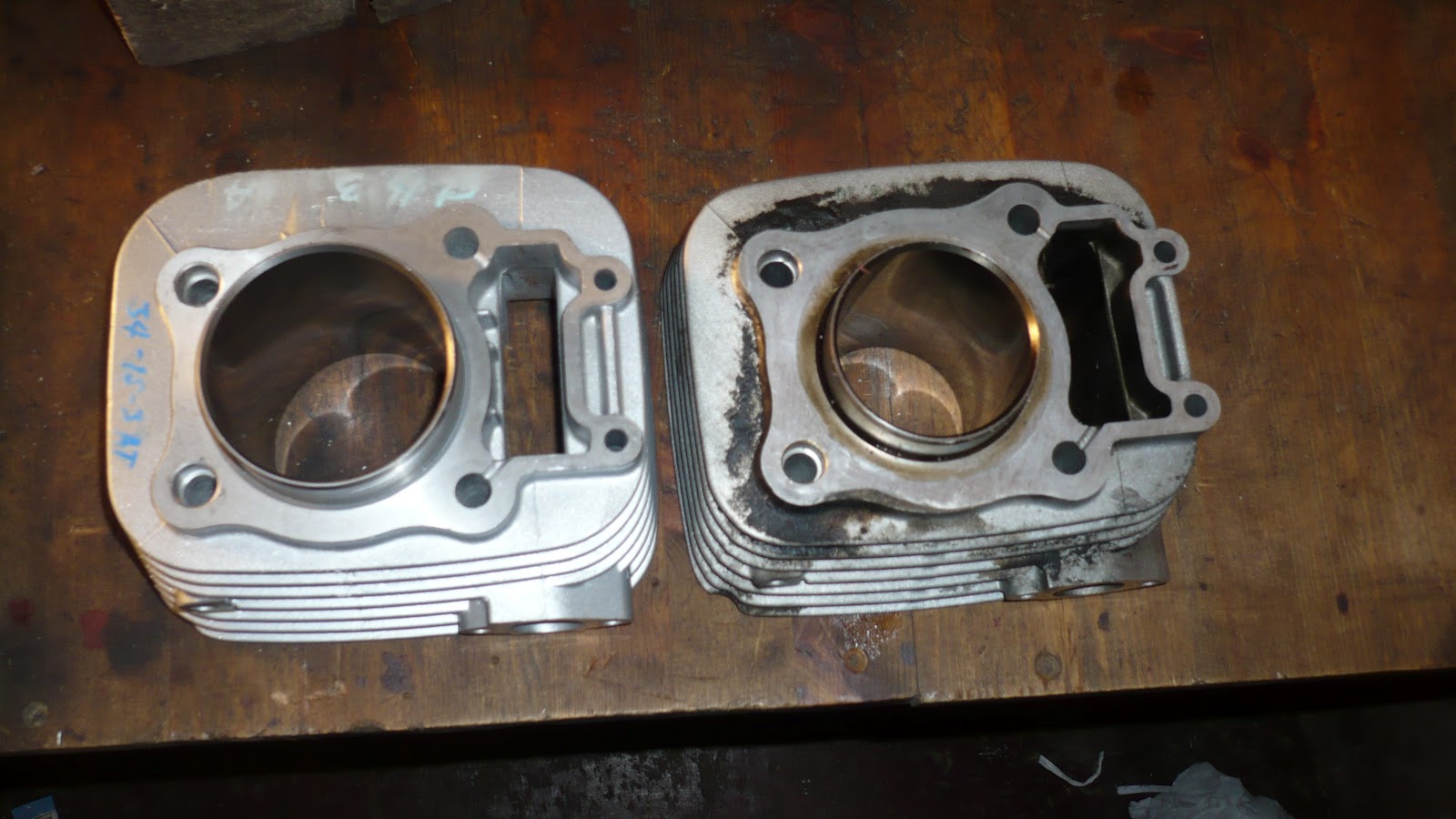
| 125cc sylinder to the left,175cc sylinder to the right |

PISTON REMOVAL
Now
you need to remove the piston. Pry out one of the locking clips that
secures the piston pin, and then press the pin out on that side.
CRANKSHAFT CHECK
 Carefully
check the crankshaft's condition for wear. The connecting rod is the
rod that the piston is fastened to, and is a part of the crankshaft
assembly. If there is any slack up-down wise, you need to give your
crankshaft assembly an overhaul, which implies a lot more work, and a
new con-rod set. The good thing about it, is that you must then buy a
bn175 con rod set, and that means the con-rod's upper hole matches
perfectly the bn175 piston that your are going to use.
Carefully
check the crankshaft's condition for wear. The connecting rod is the
rod that the piston is fastened to, and is a part of the crankshaft
assembly. If there is any slack up-down wise, you need to give your
crankshaft assembly an overhaul, which implies a lot more work, and a
new con-rod set. The good thing about it, is that you must then buy a
bn175 con rod set, and that means the con-rod's upper hole matches
perfectly the bn175 piston that your are going to use.
If
the con-rod and crankshaft assembly appears to be in a good
condition, you are now ready to fit the big bore set.
Installing
piston rings
Start
with installing the piston rings to the piston from the big bore set.

This
is quite a complicated procedure,and should be undertaken by a
professional mechanic. However, the system goes like this:
There
are 5 rings inside the package. The 2 more solid rings are for the
upper 2 grooves of the piston. They are marked,so you can see which
one goes on top,and which one comes in the second groove. Check that
each of these top rings fits perfectly and be pushed all the way in
for their ends to meet with no big space. Then there is a third
groove where the 2 thin rings called "oil ring rails" plus
the funny looking oil-ring will come too.
 |
| This is a bn125 piston with the rings installed |
Install
first this strange looking ring, called the oil ring
expander,in the bottom piston ring groove. Then slide the other 2
small rings into the same groove,one over and one under the expander
ring. Then install the rings of the upper 2 grooves. Take great care
not to break the rings. If not treated correctly,they will break!
 |
| Positions of the openings of the different piston rings. |
When
all rings are finally on the piston, arrange the openings of the
rings like this illustration shows: Upper ring (A)faces forward.
Second ring's opening (B) faces backwards. Upper oil ring rail faces
forward. Oil ring expander's opening faces backwards. Lowest oil ring
rail faces thus forward. The details about the correct angles can be
found in the workshop Manual page 132. Use a small pinpointed tool to
arrange the rings like this,and be sure to check it before installing
the cylinder block on the new piston.
FITTING
THE BN175 PISTON ON TO A BN125 CONNECTION ROD
There
is an important difference between the bn125 engine and the bn175
engine. All parts are the same,except for the diameter of the piston
pin. The 125cc engine's piston pin is Ø15mm,and the BN175 pin is
Ø16mm. To avoid having to change the whole con-rod with all the work
and extra costs involved,I have developped a way to make a
"cheating". However,I will stress that this cheating may
not be very strong or stable over a long period of time,even if I
have testimonies from people who ran the bike with this system for
more than 3 year,and around 35000 kms without having any issues.
The
best is of course to change the connecting rod to be from a BN175,and
then there should be no worries concerning this matter.
My
patent is as such: I take a 15mm piston bolt,and have 2 steel
bushings from a workshop in Thailand that will be pushed into the 175
piston. The outer diameter of these bushings is 16mm,and on the inner
side they have a hole of 15mm. The 15mm pin is cut so that there is
room for both these 2 bushings,and the circlips to secure the pin not
to be pushed out.


On
the above picture I have fit the 15mm pin bolt inside the hole of the
bn125 conrod,and then I show how the reducing bushings come on each
side - only as an illustration. To actually fit the piston,you must
place it over the conrod,and then insert the 15mm pin through one of
the holes. Then push the bushings into the piston pin holes so the
busings will enter over the ends of the 15mm pin. You may have to use
some force to to this. If there is not space enough to introduce the
clips to secure the pin,gently cut off a tiny bit of it to make it
slightly shorter. When all is correct,you can fit the 2 circlips from
the BN175 piston set. The 16mm piston pin from that set is of no use
when you use this solution.
The
arrow and EX symbol on the piston top shows the direction to put it:
with the arrow and ex forward (ex=exhaust).
BEFORE
FITTING THE BIG BORE CYLINDER BLOCK
I
will recommend to bring the cylinder head to a machine shop so they
can put it in a lathe and have the cumbustion chamber machined out
from 55mm to 65mm in order for it to comply with the big piston.
If that is not possible for your machine shop, then there is another
suggestion: Have them modify the edge of the piston top itself so
that it will fit nicely into the 125 cylinder head's combustion
chamber. A third suggestion is to put 2 cylinder base gaskets
under the cylinder block, thus raising the block slightly over the
piston-top and make the necessary clearance between the piston and
the head.
PUTTING
THE CYLINDER ON THE ENGINE
Now,
when you have chosen of these options, proceed. First, check that the
surface of the crankcase is smooth, with no dirt nor any residues
from old gasket. Then put the cylinder base gasket (or 2 of them if
that is your solution). Install first the 2 dowel pins in the engine
block on the right side of the crankcase opening. Have the surface of
the cylinder's inside bore greased with engine oil. I would even
apply a thick layer of gasket cement on the upper gasket before
putting the cylinder on, to avoid leaks under the cylinder due to
minor differences that might occur between the bn125 cylinder and the
new bn175. Leaks may occur on the front left side of the cylinder bottom according to my experience. If you forget to put gasket cement, and that problem occurs when you start up the engine, you may use some 2 component compound with aluminium grains, and after having degreased the area, apply a lot of it around the whole cylinder bottom and let it harden well before you start the engine. Let the engine idle for some minutes so there is no strong pressure destroying the sealing cement while it is being hardened even more while the engine gets hot.
Now,
when gasket(s) is in place,and also the 2 dowel pins, and the piston
is properly secured on the conrod, push the piston rings with your
fingers from each side of the engine, and while pressing them
together firmly, gently slide the cylinder block over the piston and
the rings. This might be a difficult job, but be careful so no damage
is done to the rings!
Now
is the time to pick up the camchain that has been down in the left
side of the engine. Use a plastic strip or a steel wire and tie it
around the chain, so it is easier to get it from the very top. Be
also sure to install the chain guide in black color, if you removed
it. The shorter one is fastened with a bolt to the crankcase, so it
is the loose one you need to install in the correct manner.
Fit
the cylinder head gasket - new one of course! for BN175 cylinder, and
install the 2 dowel pins on the cylinder block's upper part. Then fit
the cylinder head. Take care that all surfaces are smooth and clean.
Fasten the bolts according to the workshop manual.
Timing
Now,
re-install the camsprocket and the camchain. There are marks both on
the flywheel, on the crankcase, on the sprocket and on the cylinder
head itself that are called TIMING MARKS. If these parts are not
installed correctly, the valves will break and the engine will be
destroyed. So you must check with the Workshop Manual. It is found online for free pdf download if you search for it.
But I can give you some hints:
 |
| Camshaft's position in the head when the piston is on the top |
 |
| Position of camshaft sprocket when timing. Notice the position of the small mark on the sprocket in relation to the head top. |
 |
| Timing marks on the flywheel in relation to the crankcase. The T mark on the magneto should be in this position. |
But I can give you some hints:
When
you think all is installed correctly (remember to use thread locking
cement on the bolts securing the camsprocket), then turn the flywheel
around with ur hands in the direction of the arrow on it. Be sure
there is no spark plug in the cylinder head at this moment. If all
seems to turn well, and there is no collisions between any parts (see
to it that the piston also does not hit the head),then you must
remember to install the camchain's automatic tensioner. Before
fitting it, take a tiny flat screwdriver and screw it so that the pin
of the tensioner is being forced backwards. Then keep it like that
while you install the tensioner to it's place on the back of the
cylinder block. Being sure that the camchain's timing is good will
only be evident when you then use the screwdriver to activate the
push-rod by turning it anti-clockwise. Now that the adjuster is
pushing as it should on the black guide for the chain,you can again
check all the alignment marks on the flywheel and the camsprocket.
Rotate again the flywheel,and if all is well,you are almost done.
CARBURATOR AND MAIN
JET FOR THE BIG BORE CYLINDER
In
my experience,the big bore set works fine with the original main jet
of the bn125. However,considering the great increase in the
cylinder's volume,it may be smart to install a larger main jet. I
tried - and also others - to use the standard main jet from bn175,but
it seems to drown the combustion. On the Norwegian models from the
late 1990's the standard jet is #110. I put a 117 jet with great
result. If you want to use a large jet,you must balance and increase
the air flow by removing parts of the airfiltering devices,put extra
holes in that system,or use power-filter. I recommend you leave that
to the experts.
SPROCKETS: Use
16T in the front,and 41-42T in the rear. Do NOT use the original set
up for the BN125 as it will stress the engine!
The above information is provided for my customers who wish to buy the big bore set from me. Notice that all photos but one are my own,and I keep the copyright both to them and to the conversion secrets here.
IF YOU WANT TO BUY THIS KIT FROM ME, send me an email to
john_lode@yahoo.no
IF YOU WANT TO BUY THIS KIT FROM ME, send me an email to
john_lode@yahoo.no